BUILDING A KICK-UP RUDDER
![]() NICK SUHR'S GUIDE TO
NICK SUHR'S GUIDE TO
BUILDING A KICK-UP RUDDER
The idea of having a rudder that will kick-up or flip-up when you sail into shallow water is probably as old boat building itself. I decided to put this "How to" together since there's nothing in the builder's guidebook at all. The drawings are fine as far as they go, but a couple of things that once seemed confusing now are clear. Thanks are owed to Dick Woodruff (for inspiring the building effort), Frank Larimer (for his help with the plan drawings) and Don Malpas (for his usual friendly encouragement and advice). Here goes!
Following the drawings for a standard rudder, lay it out on a 4'x4' piece of cardboard. It has to be at least that big to allow you to make the measurements at the top and draw the arc that describes the curve of the aft edge of the rudder. The important lines are the forward edge of the rudder above the waterline and the waterline itself. Use a framing square to mark off the "4"x10" angle that gives you the line for the forward edge of the rudder below the waterline. You need a good sized compass to mark the circle that shapes the bottom of the rudder. I used a string and a pencil to mark the 30" diameter arc at the back of the rudder. Mark the top of the rudder at 17" as indicated in the plans. The final dimension will be smaller, shaped as shown in the drawing for the kick-up rudder, but leave that until later when you fit the almost-final rudder to your transom. The height above the transom and the angle at which the tiller extends forward are personal to each sailor and therefore not something I plan to get into in this article.
Once the entire outline of the rudder is drawn, use a new X-acto blade to cut out the rudder template. Then trace the outline of the rudder on another big piece of cardboard. This is where you should draw all of the special lines in the plans that let you create a kick up rudder. When done, grab your X-acto knife again and cut out a template for the flip-up (bottom) part of the rudder and the top part, to which you will glue the cheeks. At this point you should also make a template for the cheeks that will be glued to the outside of the top part of the rudder and form the slot in which the rudder will pivot. Most important here is marking the point where the pivot pin will be positioned.
The drawings suggest you should drill a hole down the notch on the forward edge of the bottom of the rudder in which to tie off the line that will keep the rudder "down' while you are sailing. I experimented with this and decided it would be much easier and better to just drill down about 3/4 of an inch, and then drill on an upward angle from below on the forward edge of the rudder to meet that hole. Coat the inside of this passageway with epoxy using a pipe cleaner. If you do it this way, all you have to do is tie a knot in the line where it enters the front of the rudder instead of worrying about pins or screws. It also makes replacements a breeze instead of a nightmare! Whenever this article gets published, a few pictures will truly be worth a thousand words.
The forward edge of the top part of the rudder needs to be machined so that you can run a 1/8 inch line from the top of the forward edge of the swinging rudder up to where the tiller connects. I cut cardboard templates for the one inch deep notch shown by the plans, and for the 3/4 inch thick piece of plywood that will be glued into the notch so as to leave a 1/4 inch diameter passage through the forward edge of the top part of the rudder, as shown in the plans. Coat the notch with epoxy before you glue in the 3/4 inch filler piece, and coat the filler piece as well. I used my table saw and a 7" diameter, 1/4 inch wide dado blade to cut the notch. By the way, I used the outside diameter of the dado blade to draw the ends of the templates I made for the 1" notch and the 3/4" filler piece. I practiced on a lot of scrap wood before I had everything right, and I suggest you do the same. When you set up to do the dado cut, tape a piece of masking tape alongside the blade and mark the points (from the template for the 1" notch) where you need to start and stop the cut.
The cheeks present a special problem. According to the plans, they should each be 1/2 inch thick. Realistically, this adds up to a top part that is more than 1 3/4 inches thick (counting epoxy coats), which is thicker than the width of most pintles or gudgeons you would want to use on a Windmill. After much discourse, I decided to use some of the leftover 1/4 inch and 1/8 inch plywood from my hull and tankside construction to create the cheeks for my kick-up rudder. They turned out to be only 5/16 inches thick. This was not a problem for my rudder on which I used Race-Lite pintles, but Dick Woodruff sent me some fancy hardware (the gudgeons are on his rudder and pintles on his transom) for the kick-up rudder I built for him. Dick's gudgeons are beautiful machined black anodized aluminum, but would only fit a rudder EXACTLY 1 1/2 inches thick. Fortunately, I had some thin walnut veneer in my shop, so when I built the sandwiches that turned into his cheeks, I was able to increase the thickness just enough. This part of the building process takes a lot of time, and a lot of sanding on several coats of epoxy. Once the cheeks are glued up and sanded, hand clamp them to the top part of the rudder and use a rasp and sanding board to smooth the edges so they all match. Then slip the bottom part of the rudder into the slot to see how it fits. You might need to thin the top portion of the swinging part of the rudder at this point. By this time you should have covered all of these parts with at least two coats of epoxy and sanded them down with 80-grit paper on an orbital sander. Dick and I both chose to use West graphite epoxy for the finish coats, but that is another subject that doesn't change the basic building rules.
When the bottom of the rudder fits snugly into the clamped to portion, it's time to epoxy the cheeks to the top part of the rudder. Line the clamp on your work bench with some 3 mill plastic sheeting (to protect the wood and hardware below) and clamp the forward half together. Then clamp the rest of the surfaces together with EZ-grip and C-clamps. When the epoxy has set, file and sand off all the epoxy that may have seeped at the edges. Insert the bottom of the rudder between the cheeks again to be sure it still fits snugly but can move. Make sure the forward edge of the rudder is in line, and then take the template for the cheeks and mark with an awl the point where the pivot pin should be placed. Using a drill press if possible, drill a pilot hole through the cheeks and rudder with a 1/8 inch bit. Then put a piece of scrap under the rudder top and, using the 1/8 inch pilot hole as a guide, drill a 7/16 inch hole through the cheeks and the rudder. This will perfectly accept the outside diameter of slices off a 1/8 inch brass pipe nipple cut to thickness, which will form the bushings through which the pivot pin will pass. This size nipple is perfect for a 1/4 inch stainless bolt. If you decide - as I did - to go a little bit heavier with the bolt, after you cut pieces of the tubing just slightly longer than the thickness of the rudder and the cheeks, put them in a metal vise and drill out the nipples with a 5/16 inch metal bit. The plans suggest a 3/8 inch bolt, but I think that's overkill. Rough up the outside edges of the brass bushings with a sharp file and then set them into the holes with epoxy. Use some plastic shipping tape to seal off the bottom of each hole flush when you glue in the brash bushings. You can only do one cheek at a time. When the epoxy has cured around the sleeves, file and sand them down flush with the surfaces inside and outside of the cheeks and on the rudder, and then slip them back together. Some more filing and sanding might be needed at this point to be sure everything fits together smoothly. The 1/4 or 5/16 inch bolt should pass through. If it doesn't, position the rudder in the cheeks together, clamp everything tightly and take your drill bit and pass it back through again.
Once you have the rudder "kicking up" correctly, the only thing left to do is to tie a figure eight knot in the 1/8 inch line and thread it through the top of the swinging rudder, pass it up through the slot in the top of the rudder and then lead it to a small clamcleat positioned on the bottom of your tiller just aft of the pivot pin for the hiking stick. M&E Marine sells these for port or starboard as order # 41866 (CL 213 - starboard) and # 41867 (CL 214 port) for $3.50 on page 281 of their 1998 catalog. Port or starboard doesn't make much difference in this application. It just determines from which side the line is drawn in so it will jam in the little clamcleat.
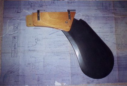
This article doesn't address the finishing you decide to do on your kick-up rudder. I built mine with a natural finish on the top and graphite epoxy on the bottom. I built Dick's with a graphite epoxy finish on the whole thing. The photos show both, but that doesn't mean you can't come up with your own ideas.
Good luck with a great but challenging project. It will add some versatility to your sailing, especially if you sometimes need to sail into shallow water or - better yet - want to enjoy some inviting beach somewhere!
Nick Suhr, #5426, 1998
PHOTOS:
Patterns
 The Result